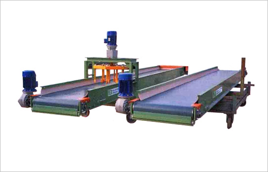
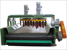
Machine functions
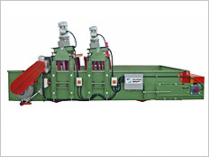
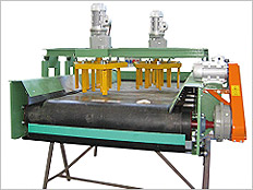
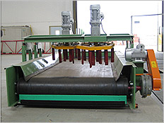
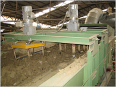
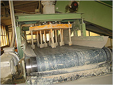
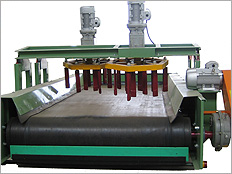
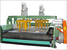
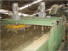
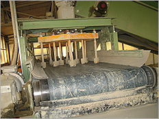
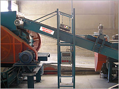
Clay dividing-levelling conveyors spread and level the clay over the whole width of the conveyor and feed the various cylinder-operated machines. The introduction of a layer of clay on the whole cylinder surface allows the optimum exploitation of the machine and a uniform wear of the cylinder on the whole longitudinal strip.
Machine description
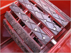
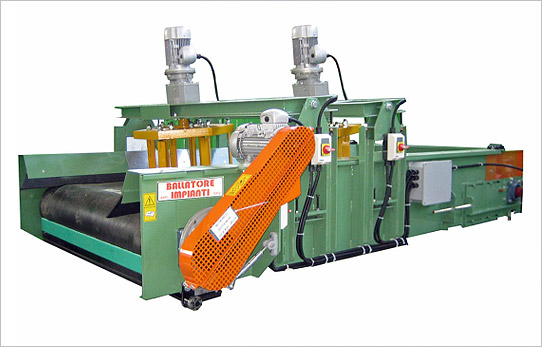
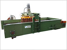
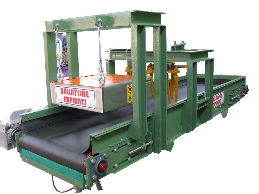
The clay dividing-levelling conveyors TNG/M + RIP series are generally flat rubber conveyors, on which the dividing-levelling device is installed and which – by rotating and properly adjusted in height and slant angle – carries out the levelling operation.
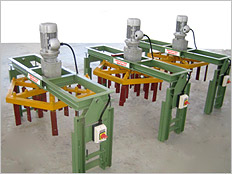
The motor-driven dividing-levelling conveyors of the RIP series are simple dividers that through a suitable frame can be installed on already existing conveyors.
| COD. | TIPO | LARGHEZZA GOMMA mm | PER LAMINATOIO mm | RIPARTITORI NUM. DIAM Ø mm | PESO Kg |
|---|---|---|---|---|---|
| F-06-04-01-00 | TNG/M-RIP 60/3 | 800 | 600 / 650 | 1 650 | 800 |
| F-06-04-02-00 | TNG/M-RIP 80/4 | 1000 | 700 / 800 | 1 750 | 1000 |
| F-06-04-03-00 | TNG/M-RIP 100/4 | 1200 | 900 / 1000 | 1 950 | 1250 |
| F-06-04-04-00 | TNG/M-RIP 120/4 | 1400 | 1100 / 1200 | 2 650 | 1650 |
| COD. | TIPO | LARGHEZZA GOMMA mm | PER LAMINATOIO mm | RIPARTITORI NUM.-DIAM Ø mm | PESO Kg |
|---|---|---|---|---|---|
| F-06-05-01-00 | RIP 65 | 800 | 600 / 650 | 1 650 | 165 |
| F-06-05-02-00 | RIP 75 | 1000 | 700 / 800 | 1 750 | 175 |
| F-06-05-03-00 | RIP 85 | 1200 | 900 / 1000 | 1 950 | 185 |
| F-06-05-03-00 | RIP 65+65 | 1400 | 1100 / 1200 | 2 650 | 330 |
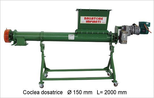
SCREW CONVEYOR
Machine functions
The screw conveyor system offers:
– substantial payload
– the possibility of horizontal, vertical and tilted conveying
– the possibility of carrying fine material (sand, cement, oxides, cereals, powders, sludge, food, etc.)
– dispersion-free conveying of both products and powder
– the possibility to transport material for short distances
Machine description
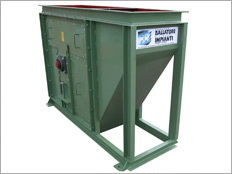
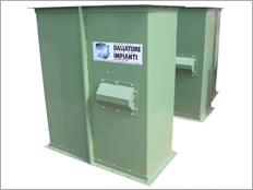
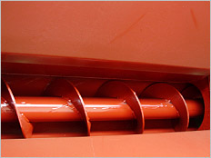
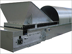
The machine is made up of a screw located within a pipe or within an open U-shaped profile. The screw conveyor is fitted with a loading mouth, through a rotation the screw conveys the material to the exit.
The rotation of the screw is provided by an electrical motor-reducer, dimensioned according to the required production, the size, length, tilting and the specific weight of the product to be conveyed.
The structure of the screw varies depending on the field of use.
| COD. | TIPO | DIAMETRO ESTERNO SPIRA | PRODUZIONE INCLINAZIONE PORTATA MAX. ° – m³/h | POTENZA INSTALLATA Kw | PESO TESTATE Kg (Medio) | PESO MEDIO Kg/m |
|---|---|---|---|---|---|---|
| F-06-07-02-00 | CT/D 150 | 150 | 60° 5 | 0,75 / 4 | 80 | 25 |
| F-06-07-04-00 | CT/D 200 | 200 | 60° 8 | 1,5 / 7,5 | 120 | 32 |
| F-06-07-06-00 | CT/D 250 | 250 | 60° 11 | 3 / 9,2 | 150 | 40 |
| F-06-07-08-00 | CT/D 300 | 300 | 60° 15 | 4 / 11 | 190 | 50 |
| COD. | DESCRIZIONE |
|---|---|
| F-06-07-50-001 | Tramoggia di carico |
| F-06-07-50-002 | Cuffia di scarico |
| F-06-07-50-003 | Cappa di aspirazione su cuffia di scarico |
| F-06-07-50-004 | Sportello di ispezione |
| F-06-07-50-005 | Sostegno carrellato per posizionamento mobile |
| F-06-07-50-006 | Struttura di sostegno fissa |
| F-06-07-50-007 | Costruzione in acciaio inox |
| F-06-07-50-008 | Controllo giri |
| F-06-07-50-009 | Variatore meccanico di giri |
| F-06-07-50-010 | Variatore elettronico di giri su motore con potenziometro |
| F-06-07-50-011 | Impianto elettrico a bordo macchina |
| F-06-07-50-012 | Quadro elettrico di comando a bordo macchina |
| F-06-07-50-013 | Verniciatura personalizzata da tabella RAL (standard verde RAL 6011) |
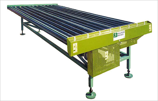
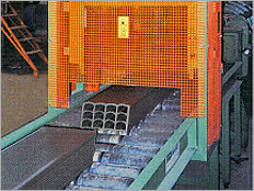
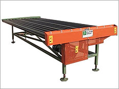
ROLLER CONVEYOR
Machine functions
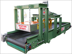
Roller conveyors are used for the handling of bricks along the cutting lines, loading and unloading of the bricks from the dryer and the kiln. Roller conveyors are suitable for handling different type medium-weight packages having a flat base.
They are used to pile-up the bricks along the various stages of the handling process, allowing to perform 90 to 180° bends by means of tapered rollers, or with chain or belt shifting systems.
Machine description
Roller conveyors are used in the most different fields, therefore the technical characteristics have dimensions and vary depending on the installation and on the type of material the conveyor is used for. Length, width, height from the ground, roller diameter, pitch of the rollers, payload, transfer speed are always suited to each individual system.
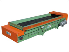
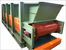
PVC BELT CONVEYORS, TNG- L/M SERIES
Machine functions
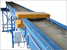
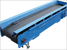
Belt conveyors with PVC belt are used where a metal structure less cumbersome than a rubber belt is required. The PVC belt slides on a sheet metal frame through a driving and tensioning head, without using intermediate rollers.
-The PVC Redler conveyor is particularly useful under box feeders in order to keep the area below clean from any discharge from the box feeder metal chain
-The PVC conveyor is used to collect scrap under the cutting lines due to its oil-repellent features.
-The PVC belt conveyor is used to convey dry bricks under the piling machine clamps.
Machine description
Belt conveyors are made out of a fully modular sturdy structural work, developed in different lengths and widths so as to give a functional and quick response to the customer’s needs. The size varies according to the different load that the conveyor must bear.
Supplied both with direct and indirect drive motor, with shafts mounted on driving and tensioning drums. Prepared for the application of several accessories at the customer’s choice – (see Technical Sheet) – they are all equipped with safety protections, head protections and cable safety end stops along the entire perimeter of the conveyor.
Each machine can be adjusted depending on the application requirements.
| CODE | TYPE | BELT WIDTH mm | OVERALL DIM WIDTH x HEIGHT mm | AVERAGE PAYLOAD m³/hrr | HEAD WEIGHT Kg | MEAN WEIGHT Kg/ml |
|---|---|---|---|---|---|---|
| F-06-03-01-00 | NPVC 40 | 400 | 500 x 280 | 10 | 60 | 34 |
| F-06-03-02-00 | NPVC 50 | 500 | 600 x 280 | 15 | 75 | 42 |
| F-06-03-03-00 | NPVC 60 | 600 | 700 x 280 | 20 | 90 | 50 |
| F-06-03-04-00 | NPVC 80 | 800 | 90 x 280 | 20 | 105 | 65 |
| F-06-03-05-00 | NPVC 100 | 1000 | 1100 x 280 | 30 | 120 | 80 |
| F-06-03-06-00 | NPVC 120 | 1200 | 1300 x 280 | 50 | 140 | 98 |
| F-06-03-07-00 | NPVC 140 | 1400 | 1500 x 280 | 80 | 160 | 110 |
| F-06-03-08-00 | NPVC 160 | 1600 | 1700 x 280 | 100 | 185 | 125 |
| F-06-03-09-00 | NPVC 180 | 1800 | 1900 x 280 | 150 | 210 | 145 |
| F-06-03-10-00 | NPVC 200 | 2000 | 2100 x 280 | 180 | 235 | 155 |
| MOTOR DRIVEN LEVELLING DEVICES RIP series CODE F-06-05 | ||||||
| CODE | TYPE | RUBBER BELT WIDTH mm | FOR ROLLING MILL mm | LEVELLING DEVICES DIAM. Ø mm | WEIGHT Kg | |
| F-06-05-01-00 | RIP 65 | 800 | 600 / 650 | 1 650 | 165 | |
| F-06-05-02-00 | RIP 75 | 1000 | 700 / 800 | 1 750 | 175 | |
| F-06-05-03-00 | RIP 85 | 1200 | 900 / 1000 | 1 950 | 185 | |
| F-06-05-03-00 | RIP 65+65 | 1400 | 1100 / 1200 | 2 650 | 330 | |
| ACCESSORIES FOR CONVEYORS CODE F-06-50 | ||||||
| CODE | DESCRIPTION | |||||
| All conveyors are supplied complete with standard multi voltage motors | ||||||
| F-06-50-01-000 | Side panels with board along the full length | |||||
| F-06-50-02-000 | Side panels without board along the full length | |||||
| F-06-50-03-000 | Rotation controlling device | |||||
| F-06-50-04-000 | Anti-sliding control | |||||
| F-06-50-05-000 | Cable safety end stop | |||||
| F-06-50-06-000 | Motor driven levelling device | |||||
| F-06-50-07-000 | Metal detector | |||||
| F-06-50-08-000 | Magnetic separator (PERMANENT MAGNET) | |||||
| F-06-50-09-000 | Reversible belt less than 10 mt | |||||
| F-06-50-10-000 | Reversible belt over 10 mt | |||||
| F-06-50-11-000 | Reversible belt over 20 mt | |||||
| F-06-50-12-000 | Motor driven car | |||||
| F-06-50-13-000 | Frame shape TILTED-FLAT or FLAT-TILTED | |||||
| F-06-50-14-000 | Hinge on belt end for tilting | |||||
| F-06-50-15-000 | Scraper with VIDIA inserts | |||||
| F-06-50-16-000 | Clay presence device | |||||
| F-06-50-17-000 | Galvanised sheet upper cover | |||||
| F-06-50-18-000 | Inspection hatch on galvanised sheet upper cover | |||||
| F-06-50-19-000 | LEXAN porthole on upper cover | |||||
| F-06-50-20-000 | Discharge hood with suction pipe connection | |||||
| F-06-50-21-000 | Belt installation frame | |||||
| F-06-50-22-000 | Wear-resistant facing on elevating bucket edging | |||||
| F-06-50-23-000 | Oil-proof rubber | |||||
| F-06-50-24-000 | Electrical system on the machine | |||||
| F-06-50-25-000 | Extra electrical wiring on the machine per linear mt |
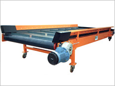
Machine functions
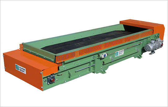
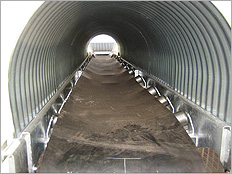
Rubber belt conveyors are indispensable to connect the production cycle, carry the clay or other materials to be channelled from one work station to another.
Machine description
Belts conveyors are made out of a fully modular sturdy structural work, developed in different lengths and widths so as to give a functional and quick response to the customer’s needs.
The structure and the various items are all bolted-on and can be supplied varnished or hot galvanized; the weld-free assembly allows quick fitting and dismantling.
The roller size varies according to the different load that the conveyor must bear.
Supplied both with direct and indirect drive motor, with drive and tension shrunk-on shafts.
Prepared for the application of several accessories at the customer’s choice (see Technical Sheet), they are all equipped with safety protections, side and lower fall prevention nets, head protections and cable safety end stops along the entire perimeter of the conveyor.
Each machine can be adjusted depending on the application requirements.
The spreader or the clay levelling machine is an indispensable accessory to attach to the conveyor in order to uniform the layer of clay on the belt, it is particularly suited on belts that feed the roller mills, so as to better exploit the rolling width of the cylinders. The spreader is composed of one or more motor-driven and tilting disks to best perform the levelling operation.
| CODE | TYPE | RUBBER WIDTH mm | OVERALL DIM WIDTH x HEIGHT mm | AVERAGE PAYLOAD m³/hrr | HEAD WEIGHT Kg | MEAN WEIGHT Kg/ml |
|---|---|---|---|---|---|---|
| F-06-01-01-00 | TNG/L* 400 | 400 | 510 x 350 | 10 | 220 | 50 |
| F-06-01-02-00 | TNG/L* 500 | 500 | 610 x 350 | 15 | 240 | 60 |
| F-06-01-03-00 | TNG/L* 600 | 600 | 710 x 350 | 20 | 260 | 70 |
| F-06-02-01-00 | TNG/M** 500 | 500 | 810 x 450 | 20 | 460 | 85 |
| F-06-02-02-00 | TNG/M** 650 | 650 | 960 x 450 | 30 | 485 | 95 |
| F-06-02-03-00 | TNG/M** 800 | 800 | 1110 x 450 | 50 | 510 | 103 |
| F-06-02-04-00 | TNG/M** 1000 | 1000 | 1310 x 450 | 80 | 530 | 125 |
| F-06-02-03-00 | TNG/M** 1200 | 1200 | 1510 x 450 | 100 | 550 | 145 |
| F-06-02-03-00 | TNG/M** 1400 | 1400 | 1710 x 450 | 150 | 570 | 165 |
| F-06-02-03-00 | TNG/M** 1600 | 1600 | 1910 x 450 | 180 | 590 | 185 |
| * L = light weight series | ||||||
| **M = modular dismountable series |

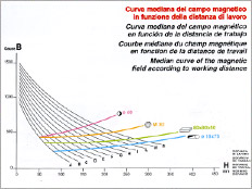
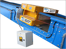
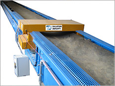
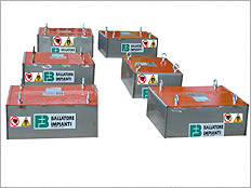
DEFERIZZATORE MAGNETICO O CALAMITA – METALDETECTOR
Funzione delle macchine
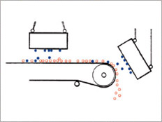
I deferizzatori magnetici o calamite sono attrezzature semplici ed economiche che servono ad asportare residui ferrosi (chiodi, pezzi di ferro, ecc) dall’argilla trasportata sul nastro.
Il metaldetector, posizionato dopo il deferizzatore magnetico esercita una funzione di controllo per garantire la totale assenza dall’argilla di qualsiasi pezzo di metallo, salvaguardando l’integrità delle macchine.
Descrizione delle macchine
Un funzionamento efficiente del deferizzatore magnetico è determinato dal volume del magnete( quantità di ferrite contenuta) la larghezza e distanza a cui è posizionato. La durata è pressoché illimitata nel tempo. Il metaldector posizionato sul nastro, esercita un campo elettromagnetico, che viene modificato quando rileva un elemento di metallo.
Un segnale (acustico o luminoso o di arresto) in base a quanto previsto nel quadro elettrico, segnalerà l’emergenza all’operatore che potrà effettuare gli interventi del caso.
| COD. | TIPO | DIMENSIONE MAGNETE mm LARG. ALT. LUNG. | ALTEZZA INSTALLAZ. mm | PER NASTRO TIPO | PESO MACCHINA Kg |
|---|---|---|---|---|---|
| 008-03-03-00 | CAL/S 50/15/50 | 500 X 150 X 500 | 150 | TNG 500 | 190 |
| 008-03-04-00 | CAL/S 50/15/60 | 500 X 150 X 600 | 150 | TNG 650 | 230 |
| 008-03-05-00 | CAL/S 50/15/70 | 500 X 150 X 700 | 150 | TNG 800 | 270 |
| 008-04-03-00 | CAL/M 50/19/60 | 500 X 190 X 600 | 190 | TNG 650 | 285 |
| 008-04-04-00 | CAL/M 50/19/70 | 500 X 190 X 700 | 190 | TNG 800 | 335 |
| 008-04-05-00 | CAL/M 50/19/90 | 500 X 190 X 900 | 190 | TNG 1000 | 430 |
| 008-05-03-00 | CAL/L 50/25/70 | 500 X 250 X 700 | 250 | TNG 800 | 440 |
| 008-05-04-00 | CAL/L 50/25/90 | 500 X 250 X 900 | 250 | TNG 1000 | 570 |
| 008-05-05-00 | CAL/L 50/25/110 | 500 X 250 X 1100 | 250 | TNG 1200 | 690 |
| 008-05-06-00 | CAL/L 50/25/130 | 500 X 250 X 1300 | 250 | TNG 1400 | 815 |
| 008-06-03-00 | CAL/XL 75/27/70 | 750 X 270 X 700 | 270 | TNG 800 | 708 |
| 008-06-04-00 | CAL/XL 75/27/90 | 750 X 270 X 900 | 270 | TNG 1000 | 915 |
| 008-06-05-00 | CAL/XL 75/27/110 | 750 X 270 X 1100 | 270 | TNG 1200 | 1115 |
| 008-06-06-00 | CAL/XL 75/27/130 | 750 X 270 X 1300 | 270 | TNG 1400 | 1315 |
| METAL DETECTOR serie MDG | |||||
| COD. | TIPO | DIMENSIONE MAGNETE mm LARG. ALT. LUNG. | ALTEZZA INSTALLAZ. mm | PER NASTRO TIPO | PESO MACCHINA Kg |
| 005-10-02-00 | MDG 50 | 1000 X 360 X 400 | 250 | TNG 500 | 45 |
| 005-10-03-00 | MDG 65 | 1030 X 340 X 400 | 250 | TNG 650 | 52 |
| 005-10-04-00 | MDG 80 | 1150 X 400 X 440 | 250 | TNG 800 | 60 |
| 005-10-05-00 | MDG 100 | 1300 X 400 X 440 | 250 | TNG 1000 | 66 |
| 005-10-06-00 | MDT 120 | 1550 X 400 X 440 | 250 | TNG 1200 | 82 |
| 005-10-07-00 | MDT 140 | 1800 X 500 X 440 | 250 | TNG 1400 | 98 |
| ACCESSORI PER METAL DETECTOR COD. 008-50 | |||||
| COD. | DESCRIZIONE | ||||
| 008-50-01-00 | Tiranti di regolazione di staffaggio | ||||
| 008-50-02-00 | Telaio fisso di installazione | ||||
| 008-50-03-00 | Telaio con guide mobili di installazioni | ||||
| 008-50-04-00 | Staffe montaggio MDG più sagomatura nastro | ||||
| 008-50-05-00 | Carter in policarbonato per MDG |

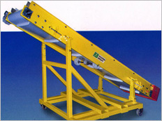
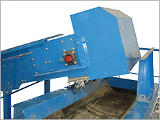
BUCKET ELEVATORS
Machine functions
Belts conveyors with PVC belt are used where a metal structure less cumbersome than a rubber belt is required. The PVC belt slides on a sheet metal frame through a driving and tensioning head, without using intermediate rollers.
Machine description
The bucket elevator is built with a modular structure in suitably thick sheet metal, to be bolted on, the structure is self supporting, inspection hatches are installed.
Fitted with a drive roller, motor and reducer, tension roller, Eletex 800/5 type rubber mat with screwed-on buckets, protection guard: drive through belts between motor pulley and reducer.
Specific accessories can be installed on the machine depending on the specific requirements, such as, for example the inspection balcony and related ladder to access the balcony
| CODE | TYPE | BUCKET DIMENSION BUCKET WIDTH mm LOADING CAPACITY lt | PRODUCTION m³/hr | INSTALLED POWER Kw | HEAD WEIGHT Kg | MEAN WEIGHT Kg/m |
|---|---|---|---|---|---|---|
| F-06-06-02-000 | ET 140 | 140 0,5 | 2 / 7 | 1,5 / 3 | 350 | 50 |
| F-06-06-04-000 | ET 225 | 225 1,6 | 7 / 15 | 2,2 / 4 | 480 | 75 |
| F-06-06-06-000 | ET 350 | 350 4,3 | 15 / 30 | 5,5 / 11 | 750 | 100 |
| F-06-06-08-000 | ET 500 | 500 6,2 | 30 / 50 | 7,5 / 15 | 1300 | 160 |
| ACCESSORIES FOR BUCKET ELEVATORS CODE F-06-06-50 | ||||||
| CODE | DESCRIPTION | |||||
| All bucket elevators are supplied complete with standard multi voltage motors | ||||||
| F-06-06-50-001 | Rotation controlling device | |||||
| F-06-06-50-002 | Anti-sliding control | |||||
| F-06-06-50-003 | Cable safety end stop | |||||
| F-06-06-50-004 | Hinge on end part for tilting | |||||
| F-06-06-50-005 | Clay presence device | |||||
| F-06-06-50-006 | LEXAN porthole on upper cover | |||||
| F-06-06-50-007 | Discharge hood with suction pipe connection | |||||
| F-06-06-50-008 | Wear-resistant facing on elevating bucket edging | |||||
| F-06-06-50-009 | Electrical system on the machine | |||||
| F-06-06-50-010 | Drums with interchangeable rubber bars | |||||
| F-06-06-50-011 | Extra electrical wiring on the machine per linear mt | |||||
| F-06-06-50-012 | Customised varnishing from RAL table (RAL 6011 green as standard) | |||||
| F-06-06-50-013 | Galvanising | |||||
| F-06-06-50-014 | Railing | |||||
| F-06-06-50-015 | Step irons to access the balcony | |||||
| F-06-06-50-016 | Bucket feature set based on the payload and on the type of product to be carried |